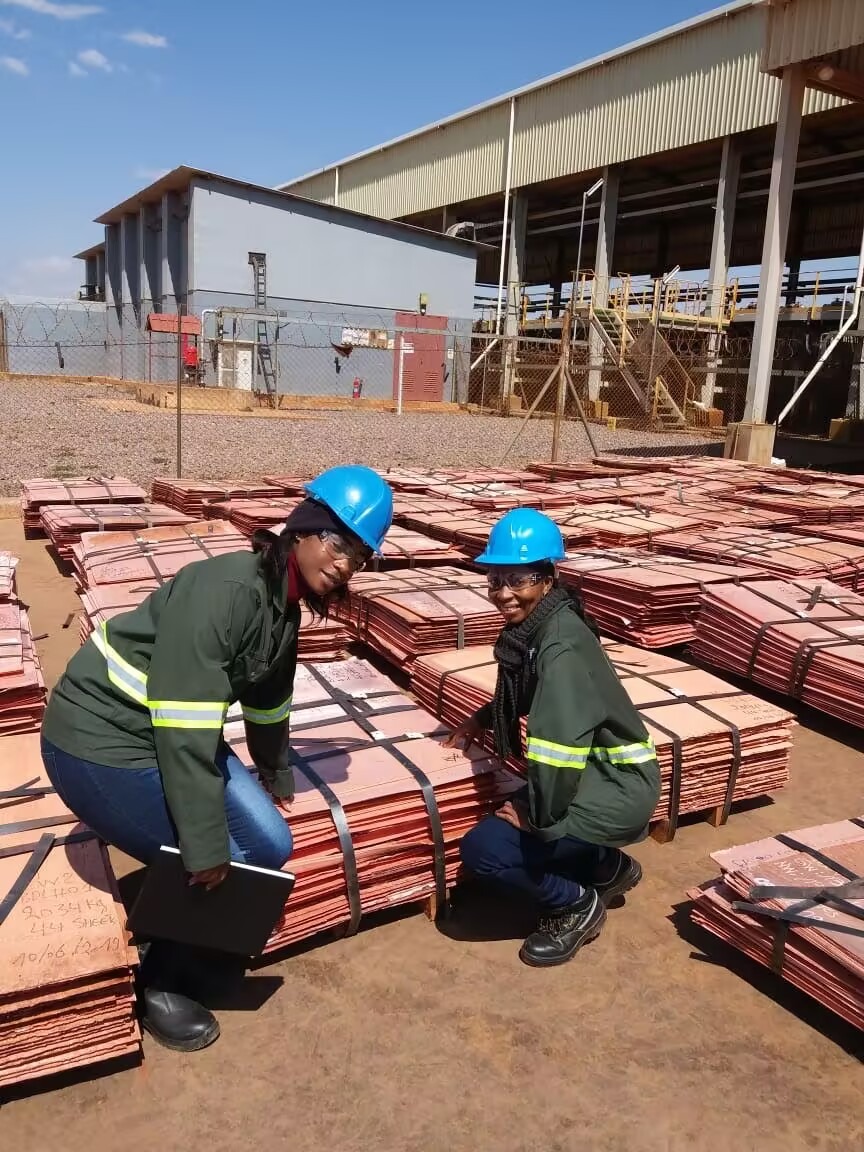


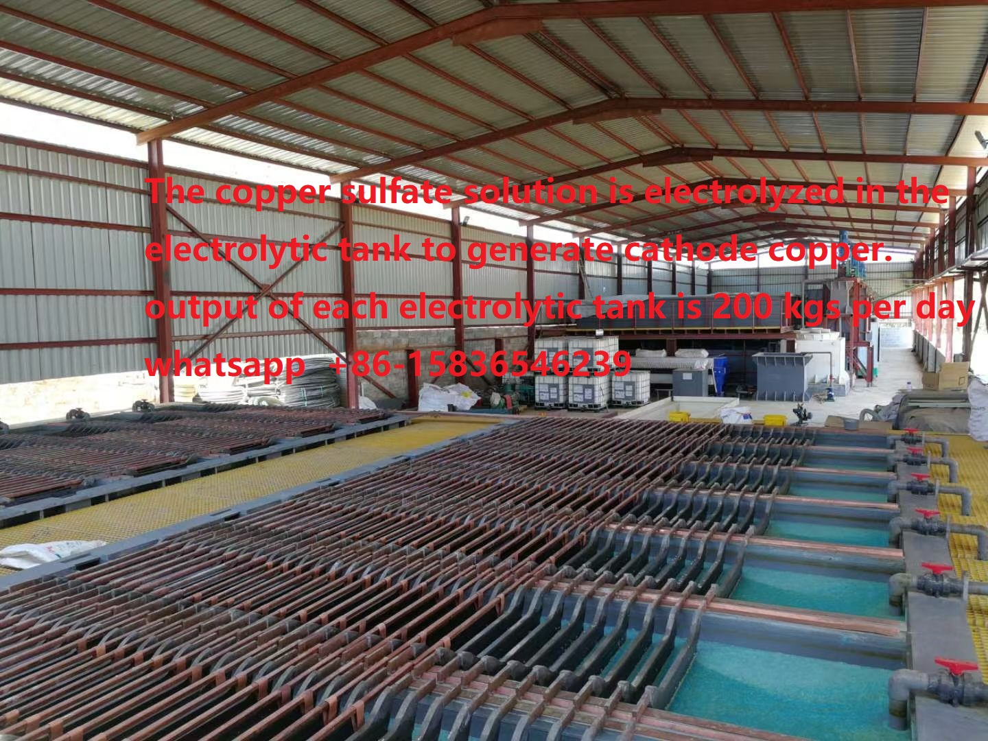
Cathode copper production line
In contemporary manufacturing, copper electrolysis plays a crucial role in creating high-purity copper cathode plates. These plates are extensively utilized in electrical engineering, electronics, and various industrial sectors due to their superior electrical conductivity and minimal impurity content. Guogao will present the technology and equipment associated with the production line for copper electrolytic cathode plates.
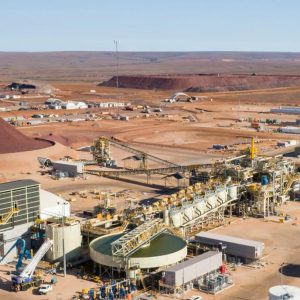
The production line for copper electrolytic cathode plates primarily includes an anode plate forming unit, an electrolyzer, a cathode plate stripping unit, a residual electrode cleaning unit, a fully automated traveling car, and a traveling car guide frame. These components work in unison to ensure an efficient and continuous production process.
In the industry, this process is conducted on a large scale. The production of electrolytic copper takes place in large electrolytic tanks filled with a copper electrolytic solution. Although even the most effective chemical methods cannot eliminate all impurities from copper, electrolytic refining can achieve a purity level of 99.99% (regardless of the method used to extract copper from its ore, the final purification is done through electrolysis).
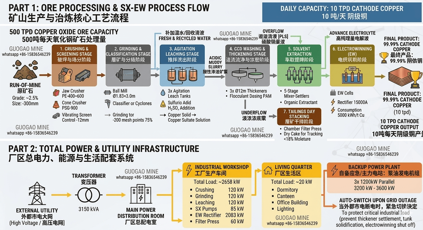
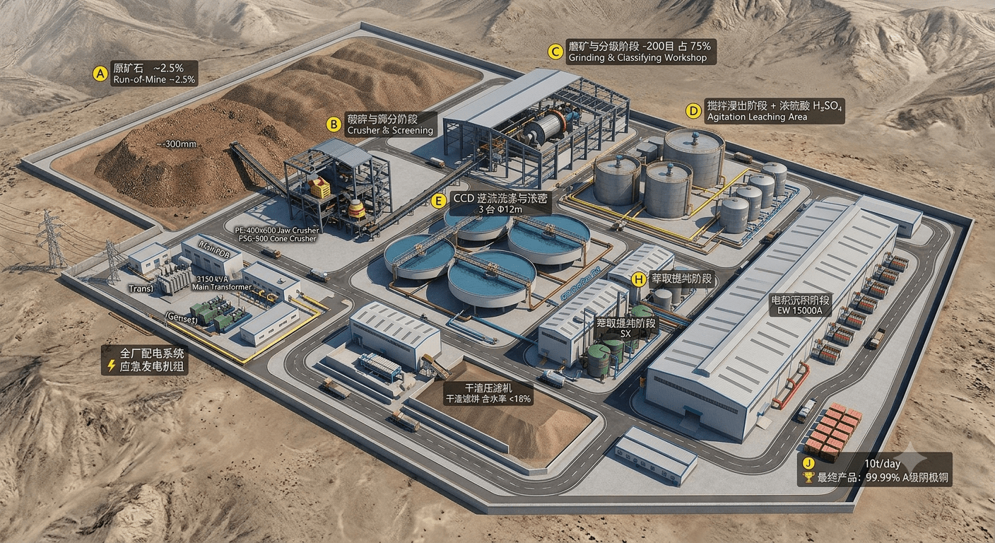
                               【 PROCESS FLOW & CLOSED-LOOP SCHEMATIC 】

【 ROM Ore 0-600mm 】➔ [ Jaw Crushing ] ➔ [ Cone Crushing + Screen ] ➔ 【 Crushed Ore ≤12mm 】
                                                                              │
【 LME Grade A Cathode 】◄ [ Stripping ] ◄ [ Hot Washing ] ◄ [ EW Cells ] ◄─【 Rich Electrolyte 】◄ [ Stripping ] ◄ [ Loaded Organic ] ◄ [ Extraction ] ◄─┤
          ▲                                             │                       ▲               │              │               │
          └─────────── Lean Electrolyte Recycle (Acid Loop 2) ──────────────────┘               └─ Raffinate ──┘               │
                                                                                                └──── Barren Organic Recycle ──┘               │
                                                                                                                                               ▼
                                                                                                                                        【 CCD Washing 】
                                                                                                                                               │
                                                                                                                                        【 Lime Neutralization 】
-
- 1.1 Primary Crushing (Jaw Crusher)
-
- Process Description: Run-of-Mine (ROM) ore (size ≤ 600 mm, moisture ≤ 5%) is uniformly fed into a heavy-duty Jaw Crusher via an apron feeder. A grizzly screen is installed ahead of the crusher to bypass fines (<100 mm), preventing over-crushing and equipment jamming.
- Control Parameters: The discharge setting (CSS) is maintained at 100-150 mm.
-
- 1.2 Secondary Crushing (Cone Crusher & Closed-Circuit Vibrating Screen)
-
- Process Description: The primary crushed product is conveyed to a high-performance Hydraulic Cone Crusher for secondary reduction. The discharged material is directed to a Double-Deck Circular Vibrating Screen. The oversize fraction (>12 mm) is recycled back to the cone crusher via a return conveyor, while the undersize fraction (≤ 12 mm) is transferred to the fine ore bin as the qualified product.
- Control Parameters: Sizing efficiency of qualified fine ore is maintained at ≥ 90%.
-
- 1.3 Wet Grinding & Classification Circuit
-
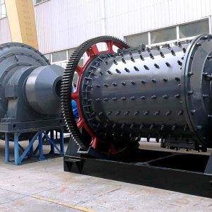
- Process Description: Fine ore (≤ 12 mm) is continuously fed from the fine ore bin via a weigh-feeder into an Overflow Ball Mill. Process water (or recycled wash filtrate) is injected at a controlled solid-to-liquid mass ratio of 1:1 to 1:1.5. The mill is charged with high-chromium steel balls (Φ 60-100 mm graded media) to grind the ore via impact and attrition.
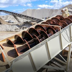
- Classification Principle: The milled slurry discharges into a Spiral Classifier (or water hydrocyclone cluster). Through gravity and centrifugal classification, the coarse underflow (coarse particles) is raked back to the ball mill feed end for re-grinding (circulating load ratio typically 200%-300%). The fine overflow (product slurry) flows by gravity to the next stage.
- Target Control Metrics: Overflow slurry fineness must strictly reach -200 mesh accounting for 75%-80% (particle size ≈ 0.074 mm), with the solid density (slurry concentration) strictly controlled at 30%-35%.
-
- 1.1 Primary Crushing (Jaw Crusher)
-
- 2.1 Multi-Stage Series Agitation Leaching
-
- Core Equipment: Consists of 3 to 5 large-scale Agitation Leaching Tanks arranged in a cascaded series. The tanks are fabricated from carbon steel lined with High-Density Polyethylene (HDPE) or Fiber-Reinforced Plastic (FRP) for anti-corrosion protection. They are equipped with dual-tier, high-displacement axial-flow impellers made of acid-resistant alloys.
- Primary Chemical Reactions:
\(\text{Malachite:\ Cu}_{2}(\text{OH})_{2}\text{CO}_{3}+2\text{H}_{2}\text{SO}_{4}\rightarrow 2\text{CuSO}_{4}+\text{CO}_{2}\uparrow +3\text{H}_{2}\text{O}\)
\(\text{Chrysocolla:\ CuSiO}_{3}\cdot 2\text{H}_{2}\text{O}+\text{H}_{2}\text{SO}_{4}\rightarrow \text{CuSO}_{4}+\text{SiO}_{2}\downarrow +3\text{H}_{2}\text{O}\) - Control Parameters: Total retention time is 4-6 hours, and the reaction endpoint pH is locked at 1.5-1.8.
-
- 2.2 Counter-Current Decantation (CCD Thickener Circuit)
-
- Process Description: The leached slurry enters a train of 3 to 4 large-diameter CCD Thickeners operating in series. Slurry and wash water flow in counter-current directions, completely washing off entrained copper ions from the solid residue surfaces.
- Tailings Handling: The underflow from the final stage thickener is pumped to a chamber filter press for mechanical dewatering. The resultant filter cake is sent to the neutralization plant.
-
- 2.3 Pregnant Leach Solution (PLS) Clarification
-
- Process Description: The overflow from the No.1 CCD thickener (raw PLS) contains fine suspended solids (TSS >50 mg/L). It is directed to a high-efficiency clarifier where flocculants are added to accelerate fine particle sedimentation.
- Qualified PLS Target Metrics: Cu²⁺: 2.5-5.0 g/L, pH: 1.6-1.8, Total Suspended Solids TSS < 10 mg/L.
-
- 2.1 Multi-Stage Series Agitation Leaching
-
- Reagent Composition & Ratio: The Aqueous phase (A) is the clarified PLS. The Organic phase (O) consists of 10%-15% hydroxyoxime-based specialty copper extractant (e.g., LIX 984N) diluted in 85%-90% high-flashpoint, de-aromatized kerosene (diluent).
- Mixer-Settler Operation:
-
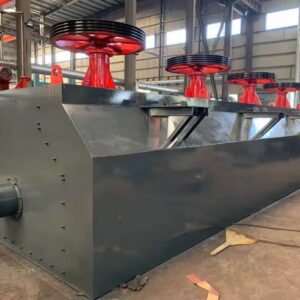
- Mixer Box: The aqueous and organic phases enter at an O/A flow ratio of approximately 1:1. A highly specialized pumping impeller provides high-shear mixing to create a micro-scale emulsion without breaking the molecular chain, driving the interfacial mass transfer:
\(2\text{R-H}_{(\text{Organic})}+\text{Cu}_{(\text{Aqueous})}^{2+}\rightleftharpoons \text{R}_{2}\text{Cu}_{(\text{Organic})}+2\text{H}_{(\text{Aqueous})}^{+}\) - Settler: The emulsion flows into an expansive, shallow rectangular settler equipped with 3D coalescer plates. Liquid velocity drops drastically, causing the phases to coalesce and separate by density.
- Mixer Box: The aqueous and organic phases enter at an O/A flow ratio of approximately 1:1. A highly specialized pumping impeller provides high-shear mixing to create a micro-scale emulsion without breaking the molecular chain, driving the interfacial mass transfer:
-
- Stream Demarcation:
-
- Bottom Layer: Raffinate. The copper-depleted aqueous phase (pH < 1.0). 【Acid Loop 1】: Continuously pumped back to the grinding circuit or agitation leaching tanks to dissolve fresh ore.
- Top Layer: Loaded Organic (LO)項目: The copper-saturated organic phase, which flows by gravity to the stripping stage.
-
-
- Process Description: The Loaded Organic (LO) enters the stripping mixer boxes where it is mixed with a high-acid Lean Electrolyte (recycled from the electrowinning tankhouse, with a sulfuric acid strength of 160-180 g/L).
- Chemical Equilibrium Shift: In a highly acidic environment, Le Chatelier’s principle forces the extraction equilibrium to reverse, stripping the Cu²⁺ ions off the organic extractant molecules:
\(\text{R}_{2}\text{Cu}_{(\text{Organic})}+2\text{H}_{(\text{High-Acid\ Aqueous})}^{+}\rightarrow 2\text{R-H}_{(\text{Organic})}+\text{Cu}_{(\text{Aqueous})}^{2+}\) - Stream Demarcation:
-
- Top Layer: Barren Organic (BO). The regenerated copper-free organic phase, pumped back to the extraction mixers for continuous reuse.
- Bottom Layer: Rich Electrolyte.
-
- Target Metrics: Cu²⁺ concentration spikes from 30 g/L up to 45-50 g/L, while the H₂SO₄ concentration is kept at 150-180 g/L.
-
-
- Deep Crud & Crud Removal (Critical Engineering Safety Gate): Before entering the electrowinning cells, the Rich Electrolyte must pass through a Dissolved Air Flotation (DAF) unit and dual-media walnut shell filters.
-
- Control Metric: Organic entrainment must be strictly kept < 2 ppm. Any organic carryover into the electrowinning cell will cause organic charring (“burning”) on the permanent cathode plates, permanently ruining the 316L stainless steel substrates.
-
-
- 4.1 Tankhouse Hardware Configuration
-
- Electrowinning (EW) Cells: Cast from high-grade vinyl ester polymer concrete, molded as a single monolithic structure. They feature high acid resistance, insulation, and high mechanical strength without requiring a separate internal liner.
- Electrodes: Cathodes are 316L Stainless Steel Permanent Cathode Plates (equipped with vertical insulating side clips and copper-clad steel hanger bars). Anodes are insoluble Lead-Silver (Pb-Ag 0.75%) multi-element alloy plates.
-
- 4.2 Electrochemical Reaction & Run Parameters
-
- \(\text{Cathode\ (Reduction):\ Cu}^{2+}+2\text{e}^{-}\rightarrow \text{Cu}^{0}\downarrow \quad \text{(Pure\ metal\ copper\ crystallizes\ layer\ by\ layer\ on\ the\ SS\ surface)}\)
- \(\text{Anode\ (Oxidation):\ }2\text{H}_{2}\text{O}-4\text{e}^{-}\rightarrow \text{O}_{2}\uparrow +4\text{H}^{+}\quad \text{(Water\ decomposes\ into\ oxygen\ gas\ while\ generating\ pure\ sulfuric\ acid\ in\ situ)}\)
- Core Parameters: Inter-electrode pitch (anode-to-cathode spacing) 95±5 mm; current density 250-320 A/m²; electrolyte temperature 45°C-50°C. Bone glue (smoothing agent) and cobalt sulfate (anode protector) are continuously dosed in micro-quantities.
-
- 4.3 Lean Electrolyte Recycle (Acid Loop 2)
-
- Post-reaction, copper drops and acidity rises (Cu²⁺: 33-35 g/L, H₂SO₄: 180-200 g/L), converting the solution into a Lean Electrolyte. It is pumped back to the stripping stage mixers to act as the stripping agent.
-
- 4.4 Automated Cathode Harvesting & Stripping Machine (CSM)
-
- Harvesting Cycle: Typically 7 to 9 days. Cathodes are harvested when the single-side copper deposit reaches 4-5 mm (approx. 45-50 kg per copper sheet).
- Automated CSM Line: A specialized insulated overhead crane lifts a full cell of cathodes ➔ transfers them to the High-Pressure Hot Washing Unit (70°C water spray removes residual acid) ➔ advances to the Automatic Stripping Machine (robotic flexing/hammering breaks the edge bond ➔ pneumatic stripping knives wedge down to cleanly separate both copper sheets) ➔ SS blanks are checked for verticality and returned to the EW cells.
- Final Product: The stripped copper plates are automatically weighed, laser-marked, strapped, and bundled into market-ready LME Grade A Standard Copper Cathodes (Purity ≥ 99.99%).
-
- 4.1 Tankhouse Hardware Configuration
| Section Name | Sizing Core Metric | Calculation Formula / Design Boundary | Final Engineering Equipment Spec / Parameter |
|---|---|---|---|
| Crushing & Grinding | Daily Ore Feed Throughput | \(\frac{10,000\text{\ tonnes}}{330\text{\ Days}\times 2.5\%\text{\ Grade}\times 90\%\text{\ Leaching\ Recovery}}\) | 1,346 Metric Tonnes/Day (Equipped with a 750 kW Overflow Ball Mill) |
| Solvent Extraction | Aqueous Phase Flow (A) | \(\frac{1,262\text{\ kg/h\ (Hourly\ Metal\ Yield)}}{0.90\times (3.5-0.3)\text{\ kg/m}^{3}}\) | 438 m³/h (Equipped with a ≥ 90 m² settling area per Mixer-Settler stage) |
| Electrowinning | Total DC Current Demand | \(\frac{1,262,000\text{\ g/h}\times 96485}{31.75\times 92\%\text{\ Current\ Efficiency}}\) | 4,166,400 Amperes⋅Cells (Equipped with a 26 kA Rectiformer + 160 EW cells) |
-
- Adaptive Leaching Acidity Loop (pH Loop): Heavy-duty antimony or specialized glass pH electrodes are installed in the leach tanks. The DCS monitors pH in real-time. If the pH rises ≥ 1.8, it ramps up the variable frequency drive (VFD) of the concentrated sulfuric acid diaphragm dosing pumps, locking the pH at 1.6 ± 0.1.
- Automated SX O/A Ratio Stabilization: Electromagnetic flowmeters are installed on the PLS lines, and Coriolis mass flowmeters on the organic lines. The DCS computes water-phase fluctuations instantly and alters the VFD on the organic pumps, forcing the Organic-to-Aqueous (O/A) ratio to stay within 1:1 – 1.05:1 to prevent catastrophic phase inversion or emulsion.
- Infrared EW Short-Circuit Group Monitoring: High-resolution infrared thermal imaging cameras are mounted on the overhead harvesting crane, automatically scanning the cell busbars every 30 minutes. If a cathode plate displays an abnormal temperature spike due to dendrite short-circuiting, the DCS sounds an alarm and highlights the shorted cell on the HMI screen for manual clearance.
-
- Acid Mist Abatement System: EW cell surfaces are blanketed with 3 layers of hollow plastic polypropylene balls, and a specialty FC-102 fluorocarbon surfactant is dosed into the rich electrolyte to create a dense trapping foam. High-volume lateral draft hoods pull air to a scrubbing tower where it is neutralized by caustic soda spray before atmospheric venting.
- Tailings Neutralization & Detoxification: High-acid filter cakes discharged from the filter presses pass into neutralization tanks where lime milk (\(\text{Ca(OH)}_{2}\)) slurry is introduced under intense agitation, neutralizing the pH to 7.5 – 8.0 and converting residual free acid into inert gypsum (CaSO₄), allowing safe disposal into lined tailings storage facilities.
- Plant-wide Anti-Corrosion & Zero Liquid Discharge (ZLD)|: Standard carbon steel is prohibited for all process piping; instead, PPH (Polypropylene Homopolymer), CPVC, or advanced PVDF are specified. All plant floors are constructed with acid containment bunds lined with a 5mm thick epoxy fiberglass coating (3-cloth, 5-coat spec). A 2,000 m³ acid-proof initial stormwater catchment pond captures all floor washdowns and rainwater, which is neutralized and routed back as grinding process water, achieving 100% Zero Liquid Discharge (ZLD).
This complete technical document outlines the process flow, sizing math, and safety parameters for a standard 10,000 TPA copper hydrometallurgical plant. If you are preparing this for a formal commercial tender or feasibility study, we can proceed to add:
-
- A Master Equipment List (MEL) with recommended pump models, valves, and specific material grades.
- A customized Purification Upgrade Modality if your specific ROM ore has high iron, manganese, or arsenic content.